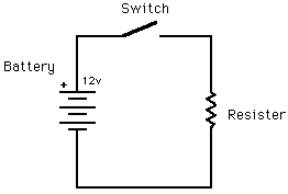
 The basic circuit is very simple (don't worry it gets more complicated).
The amount of power dissipated by a
resistor is calculated by the formula:
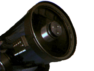
So there needs to be a little box to hold the switches. I originally planned to mount the box inside one of the fork arms, but the difficulty of neatly running all the wires across the Declination bearing led me to decide to simply stick the box on the side of the scope tube near the corrector end. This way only the power input wire needs to worry about the scope's motion. And so long as we have a box we might as well add some LEDs as pilot lights and a connector for the power input so the wire can be removed with the heater is not in use.
 The basic circuit is very simple (don't worry it gets more complicated).
The amount of power dissipated by a
resistor is calculated by the formula:
P = E * I
E = I * R
    E2
P = -
    R
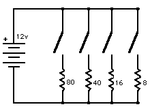
But we wanted four separate heaters with varying power levels. Doing the math gives
about 80, 40, 16, and 8 ohms for the resistors.
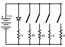
Now we add the main pilot light. The extra resistor in series with the LED is
to limit the current thru the LED to its rated level; it works out to
about 1000 ohms (usually written 1k ohm).
(Electronics cognoscenti will note that I've used the wrong symbol for a LED;
sorry 'bout that but I couldn't find one to paste in so I used the symbol for a
plain diode.)
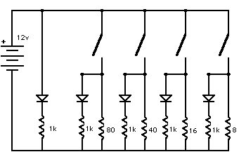
But, of course, we want separate pilot lights for each heater, too.
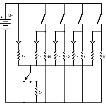
And finally a switch to dim or turn off the lights during star parties.
(Where wires cross
without a dot there is no connection.)
There are two more interrelated considerations (and then we're ready to start soldering). First, we want to distribute the heat evenly across the whole circumference of the corrector (heck, we would like to distribute across the whole surface, but putting resistors in the middle of the aperture wouldn't do). And secondly, a resistor can't dissipate an infinite amount of power; they are rated for a particular maximum amount of power dissipation. So we use a number of resistors in combination for each of the heater resistors in the diagram above.
 The resistance of two
resistors in series is simply the sum of their individual resistances.
So we implement the 80-ohm resistor with 16 5-ohm resistors in series.
The resistance of two resistors in parallel is given by the formula:
    1
Rt = -------
     1     1
     -  +  -
       R1    R2
 So we implement the 40-ohm resistor with 8 5-ohm resistors in series each of which
is a pair of 10-ohm resistors in parallel.
Similarly, the 16-ohm resistor is constructed of 8 sets of 5 10-ohm resistors and the 8-ohm resistor is 8 sets of 10 10-ohm resistors. For better heat distribution, the 16-ohm resistor is physically divided into two: 8 pairs plus 8 triplets. Similarly, the 8-ohm is 16 pairs plus 16 triplets.
In all cases, each individual resistor dissipates less then 1/4 watt so small 1/4 watt resistors can be used. And there are a sufficient number of resistors to distribute the heat evenly.