A Do-It-Yourself
Dew Heater
for an SCT
Construction
Construction
The Resisters
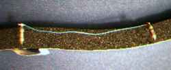
Cut the weather stripping to length to fit on the inside of your scope tube (41.5 inches)
and form into a loop with the sticky side out.
Make sure it fits snugly; too big is better than too small
(witty remark elided; this is a G-rated project).
Stick the ends together with glue.
 Bend the leads of all the resisters.
Place the 16 5-ohm resisters evenly around (every 2.6 inches) by sticking the leads
into the foam.
This establishes the spacing for the remaining resisters so be reasonably careful
to get each gap approximately the same size but
a few millimeters one way or the other won't matter.
Bend the leads of all the resisters.
Place the 16 5-ohm resisters evenly around (every 2.6 inches) by sticking the leads
into the foam.
This establishes the spacing for the remaining resisters so be reasonably careful
to get each gap approximately the same size but
a few millimeters one way or the other won't matter.
Now the long tedious part -- placing the remaing 136 resisters and
attaching all the wires.
It is much easier to place one resister (or pair or triplet) at at time rather
than placing them all first and then running the wires.
Now you would think that the logical thing to do would be to start with one end and
attach the wires from the control box to the first set and so on.
But this would mean that the long wire ends going to the
control box would be flopping
around while we do the rest of the job.
So the clever thing to do is to start with the middle and do long floppy wires on
the ends last.
Here is the wiring diagram:
This diagram represents 1/8 of the heater.
The first section connects to the controller box,
each section connects to the next
and the last connects back to the controller box.
The 2, 4, 8, and 16 watt units are represented by blue, green, yellow and red wires
respectively. The parallel sets are physically spaced out to more evenly distribute
the heat. Though they look separate here, they will be wired in parallel in the
controller box.
Cut 16 blue wires about 3" long, 32 red and 16 yellow wires 6 1/4" long,
and 16 green wires about 8 1/2" long; strip one end of
each (they will be a little long so you'll need to strip the other
end at the right length when it is attached.
 Here's the first wire installed, connecting two of the 5-ohm resisters.
Only 71 to go!
Wrap the ends of the wire around the leg of the resister and solder as near the top
as possible. Don't worry about frying the resister with the soldering iron; they're
pretty tough. Do be careful to make good joints.
Check to make sure each solder joint is OK.
We're putting wires on only one side of each of the resisters in this first section;
the other side will be the long wires from the controller
box which are installed last.
Here's the first wire installed, connecting two of the 5-ohm resisters.
Only 71 to go!
Wrap the ends of the wire around the leg of the resister and solder as near the top
as possible. Don't worry about frying the resister with the soldering iron; they're
pretty tough. Do be careful to make good joints.
Check to make sure each solder joint is OK.
We're putting wires on only one side of each of the resisters in this first section;
the other side will be the long wires from the controller
box which are installed last.
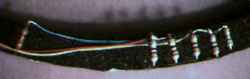 Here are the second and third wires installed on 10-ohm resisters.
Notice that each wire connects to two adjacent resisters
so that they are connected in parallel forming a pair.
This is easily done by stripping
enough insulation off so that the bare end can be soldered to both resisters.
(The triple work the same way, just make the bare wire a little longer.)
All wires are routed underneath the resisters.
Here are the second and third wires installed on 10-ohm resisters.
Notice that each wire connects to two adjacent resisters
so that they are connected in parallel forming a pair.
This is easily done by stripping
enough insulation off so that the bare end can be soldered to both resisters.
(The triple work the same way, just make the bare wire a little longer.)
All wires are routed underneath the resisters.
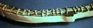
 Here's the first section done except for the wires from the controller box.
Note that the green wire connects two resisters in parallel as shown in the
wiring diagram.
Here's the first section done except for the wires from the controller box.
Note that the green wire connects two resisters in parallel as shown in the
wiring diagram.
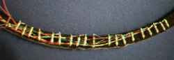
Here's one of the middle sections completely done:
 Note that all the wires are routed under the resisters. Don't worry about the
fact that it gets to be a tangled mess, in the end you won't see it.
Note that all the wires are routed under the resisters. Don't worry about the
fact that it gets to be a tangled mess, in the end you won't see it.
Now for the end sections.
Cut 4 red wires, 2 yellow, 1 green, 1 blue, 8 black to 16" length.
Strip one end (we'll strip the other when its cut to precise length).
Solder them to the last sections as usual but with the ends hanging loose.
All 16 ends should come out between one pair of resisters.
Bend them over and lay them all side-by-side into a sort of flat ribbon cable (or
just use a piece of small ribbon cable but make sure its thin enough that you
can still fit your lens cap and dewshield).
Its not really necessary to use so many black wires but one is not enough to carry
the full current when all the sections are working and using 8
felt symmetrical to me.
Testing
There are so many connections here that a mistake is likely.
So check carefully before proceeding.
Twist all the black wires together (or hold them tightly in an alligator clip) and
attach to one side of your meter.
Then check the resistance between the black ends and each of the colored wires.
Blue should read 80 ohms; green 40; one of the yellows and two of the reds
should be 40 ohms and the others 27 ohms. Don't worry if they're off by less than
10 percent.
 When the ring is all done and you've verified that its wired correctly,
make sure that all the wires are routed inside the resister legs and then
push all the resisters down as far as they will go.
Then cut the excess ends of the legs off on the other side of the foam.
This is the side you will see so be careful. Compress the foam a bit with your
cutters so that the leg is cut off a millimeter or so beneath the surface.
When the ring is all done and you've verified that its wired correctly,
make sure that all the wires are routed inside the resister legs and then
push all the resisters down as far as they will go.
Then cut the excess ends of the legs off on the other side of the foam.
This is the side you will see so be careful. Compress the foam a bit with your
cutters so that the leg is cut off a millimeter or so beneath the surface.
The Controller
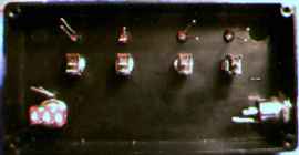 Now for the controller box (this is a lot more fun and a lot less work).
Drill holes to mount the LEDs, switches, and the connector.
Cut a small slot for the wires to come in
out of the edge of the box on the
end opposite the power input connector.
Install all the parts and tighten (neatness freaks will make sure the nuts visible
on the front side are all lined up with their faces parallel).
Now for the controller box (this is a lot more fun and a lot less work).
Drill holes to mount the LEDs, switches, and the connector.
Cut a small slot for the wires to come in
out of the edge of the box on the
end opposite the power input connector.
Install all the parts and tighten (neatness freaks will make sure the nuts visible
on the front side are all lined up with their faces parallel).
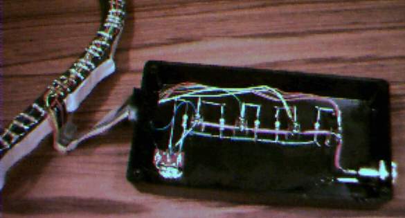 Wire it all up according to the diagram above.
The only tricky part is making sure that you get the
polarity of the LEDs correct. The LEDs I used had the two legs
different lengths and were clearly marked on the package which is
which. Be careful, you may fry them if you get it backwards.
Wire it all up according to the diagram above.
The only tricky part is making sure that you get the
polarity of the LEDs correct. The LEDs I used had the two legs
different lengths and were clearly marked on the package which is
which. Be careful, you may fry them if you get it backwards.
Measure for the lengths of the wires by doing a trial installation.
Cut them all the same length and then trim them just before soldering.
Twist together the 4 red wires so that their resister
nets are in parallel. Ditto for the 2 yellows.
All the blacks connect to the negative side of the power input connector (with
one looping thru to connect the LED dimmer switch.
Put a piece of tape over the wire as it comes over the edge of the box.
More Testing
Hook it up to a battery and test. The resisters should get reasonably hot
but not so much as to damage the foam or smell bad. This is a good chance to
play around with your meter and measure the current draw. You will notice that
your battery voltage (and thus the power dissipation) is anything but constant.
Such is life. If we really cared about precise power levels we could use a
regulated power supply but this is just a heater, after all. If your battery
voltage drops too much just switch on the next higher power setting!
Final Installation
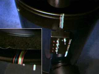 Remove the backing from the weather stripping and
install the ring around the edge of the corrector plate mounting ring.
Don't worry about making shorts; the mounting ring (on an 12" LX200, anyway)
is annodized aluminum and will not
be a problem. (But if your scope has a plastic ring it may melt!
So check carefully.)
Press it down firmly to insure good thermal contact.
Fold the wires so they lie flat and wrap around the edge of the tube and back down
the outside.
Cover the wires with a piece of black electrical tape.
Stick the controller box down with double sided sticky tape.
Make a power cord with a male DC coaxial plug on one end, an inline fuse holder
in the middle (with a 3-amp fast acting fuse) and whatever is
convenient on the other.
Remove the backing from the weather stripping and
install the ring around the edge of the corrector plate mounting ring.
Don't worry about making shorts; the mounting ring (on an 12" LX200, anyway)
is annodized aluminum and will not
be a problem. (But if your scope has a plastic ring it may melt!
So check carefully.)
Press it down firmly to insure good thermal contact.
Fold the wires so they lie flat and wrap around the edge of the tube and back down
the outside.
Cover the wires with a piece of black electrical tape.
Stick the controller box down with double sided sticky tape.
Make a power cord with a male DC coaxial plug on one end, an inline fuse holder
in the middle (with a 3-amp fast acting fuse) and whatever is
convenient on the other.
Done!
Main page . . .
Tools and Materials . . .
Theory
Bill Arnett; last updated:
1996 September 17
; suggestions or corrections appreciated