Ptolemy's Cafe
Background
Like so many amateur astronomers, I've always wanted to have my own
permanent observatory. Of course, we would all like to have one on
top of Mauna Kea but the real world intervenes and we must make
compromises. So mine is in my backyard in the middle of the San
Francisco Bay Area's huge light dome. Well actually, at the edge of
it; I'm located in the hills between the ocean and the bay so there's
no city to the west of me and little to the south. But my house and
my neighbors' trees block some of my horizon. Not perfect but good
enough.
I knew from the beginning that I wanted a roll-off design, not a dome.
I like the feeling of the open sky above me and the climate here is
mild enough (rarely much below freezing) that a dome is not a requirement.
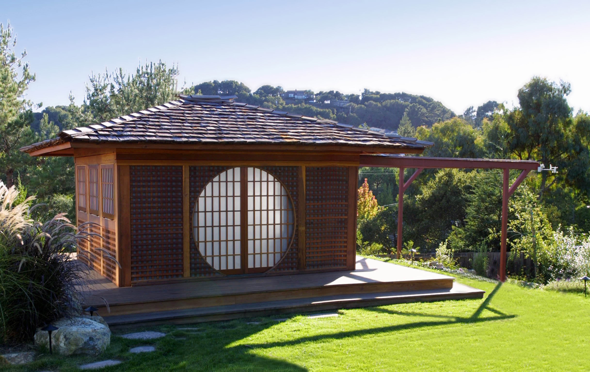
But equally importantly, I wanted it to be aesthetically pleasing. After
all, it dominates my backyard. So I decided on a "Japanese tea house"
look and designed the rest of my landscaping to match.
There were two major tradeoffs I had to make. First, having the
roll-off support structure on the north side as is traditional was out
of the question. It would have been in the middle of my lawn. So it is
on the west side where it is least visible from my house (and
fortunately, not too bad for my neighbors, either).
Second, between the "tea house" design and the building codes and a
pretty conservative structural engineer the structure got more massive
than I would have liked. The engineer insisted on making it out of
steel which greatly increased the cost (but at least I can use it as a
shelter in an earthquake :-) . It wasn't possible to have the whole
south wall fold down (as is also commonly done) so I have to make do
with looking through fold-down windows. But the posts and tops of the
walls are pretty thick and obstruct more sky than I would have liked.
I partially compensated for this by designing a ridiculously
complicated pier which allows me to move the telescope up and down to
get different angles through the windows and over the walls.
Building the observatory was part of a larger project to landscape the
entire yard. Getting architects and plans and permits and contractors
all arranged took over a year before we actually started the work.
Plans
The observatory is 14 feet in the east-west direction and 11 1/2 feet
in the north-south direction (interior measures). (And it is lined up
with the true directions within a few minutes of arc.) The original
plan called for 12x10 feet interior measure but by happy accident
interior and exterior measurements got swapped a couple times and I
gained a few square feet :-) This gives me plenty of room to mount two
scopes on piers, have some storage and working area and still move
around. It is surrounded by a 4 foot wide deck which is about 18
inches above the surrounding ground level. The walls are just under 7
feet high with the roof open. The door is on the north side. There
are fold-down windows on the other three sides.
There is one giant block of concrete beneath the floor with three sets
of pier attachment bolts. Thus I can have one scope in the middle or
one on each end. This pier is not in contact with the rest of the
structure; I can jump up and down on the floor without affecting the
scope at all.
I adapted the rolling roof design from one I found on the Internet.
There are four 6" diameter cast iron V-groove wheels on each side.
The wheels run on steel angles welded to the top of the main
structural supports. Each wheel has a 1000 lb. load rating. This is
not as much overkill as it seems; the roof is HEAVY.
I did a lot of thinking about the opening mechanism. I had always
wanted a motorized one and when the roof was completed it was clear
that a motor was a requirement, not an option. The roof rolls nicely
and quietly but it takes a lot of effort to get it moving. I had an
old 1/2 horsepower residential garage door opener lying around so I hooked it up with a temporary
kludge and much to my surprise it moved the roof easily.
I didn't want to have chain go through the wall and be exposed to the
weather. So I spliced the chain to some plastic coated steel aircraft
cable. The idea is that if the distance the roof has to travel (17
feet) is less than the distance from the sprocket to the point where
the cable/chain must go through the wall then only cable need pass
through. This meant folding the chain/cable path once but that turned
out well anyway since it put the opener itself down on the floor where
it's easy to work with. The chain/cable passes over the motor
sprocket, up the wall and over a spare wheel to make the 90 degree
turn, along the entire length of the north wall to an idler pulley
attached to the far western support post where it makes the U-turn for
the return path.
Attaching the cable to the roof was also a little tricky. If it was
attached solidly then the roof's inertia would put a huge shock load
on the motor and its gears. But if I simply put a spring in the middle
of the cable then it wasn't possible to get the chain/cable tight
enough to prevent it from jumping off the motor's sprocket. The answer
is this: the chain/cable itself makes a complete loop with no springs
so it can be tightened (via a turnbuckle at the western idler pulley)
but it is attached to the roof with springs. (This is similar to the
way the opener was originally intended to attach to a garage door but
with much heavier springs.) It also seems to work better with
compression springs rather than the more obvious extension ones; with
compression springs there's a limit to the amount of stretch and so
the spring doesn't get stretched beyond its elastic limit. The result
works quite well. It stays tight and runs smoothly but springs three
or four inches on starting and stopping with no apparent stress on the
motor.
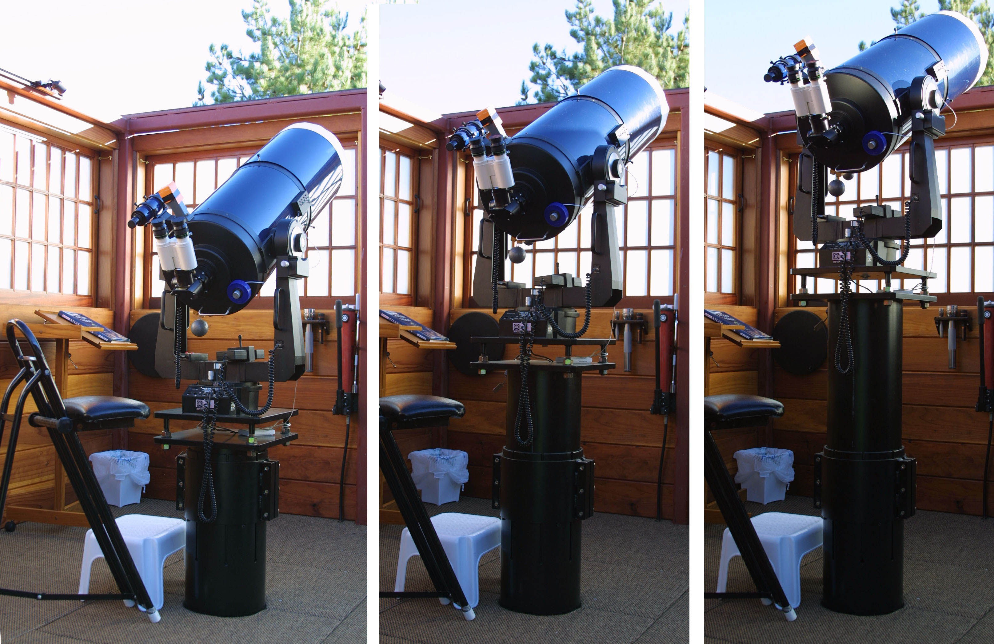
My LX200 sits on top of a telescoping steel pier which sits on top of
the concrete pier beneath the floor. The idea is to be able to move
the scope up and down to get the optimum angle through or over the
windows for objects near the horizon. It's all steel, 10" ID for the
bottom section, 10" OD for the top section. The two parts are normally
clamped together with a massive steel collar. The top section sits on
a long throw hydraulic jack inside the bottom section which is
operated an external hand pump mounted on the wall. I can loosen the
collar, pump it up (or let it down) as much as 20 inches, and
retighten the collar in less than a minute. Were I taking long
exposure photographs I would have to redo my polar alignment but for
visual work it stays aligned well enough to not matter.
Construction
Building the observatory was too big of a job for me alone; I hired a
contractor. The project took more than 10 months from the first day of
digging to the installation of the last cabinet. That seems like a
long time but it would never have happened at all if I had tried to do
it myself!
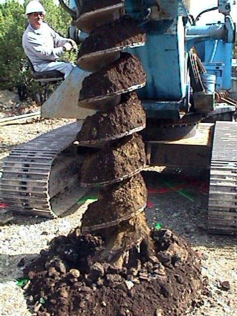
Eight 16" diameter holes and two 24" diameter holes were drilled 8'
deep and filled with reinforced concrete to support the steel frame of
the building. Plus we dug an additional 24" hole 10' deep for the
telescope pier itself. Our "soil" is very rocky; these 11 holes took
a day and half for a giant (and expensive) drill rig mounted on a huge
tracked vehicle.
A steel reinforcing bar cage was built for each hole then lowered in
place and supported a few inches off the ground before the concrete
was poured.
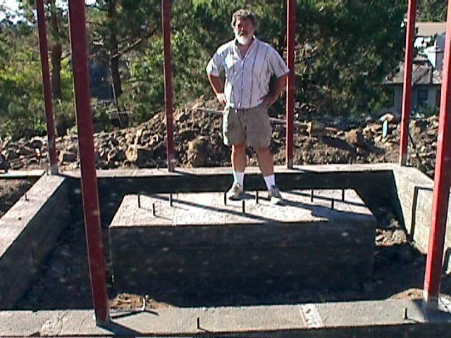
The scope pier support is a roughly "T"-shaped block consisting of the
24" diameter 10' deep base and a rectangular block on top (all
connected with more rebar); it's about 4 yards of concrete altogether.
It has three sets of three 18" long 1" diameter steel bolts for
attaching the steel telescope support pier. These bolts are mostly
embedded in the concrete with big washers at the bottom to help hold
them in place. I held each set of bolts in place with a piece of
plywood while the concrete set up. And I saved the plywood to use as
a template for the bottom of the steel pier which was built many
months later.
The structural strength of the building is provided by eight 3" square
steel tubes bolted onto the concrete piers and encased and connected
by reinforced concrete grade beams. Two more steel tubes hold up the
roll-off support rails. All these are connected at the top by more 3"
tubes and welded to form a complete steel box frame. But even with
all that steel the structure would vibrate quite a bit when given a
good kick; it got MUCH stiffer when the wooden sheer panels were added.
A flat plate and a 90 degree angle sit on top form the track on which
the wheels run. The flat plate fits in a slot in the outside roof beam
to prevent the roof from going up in a strong wind. (I'm not sure the
"lift off protection" was necessary but we do get pretty strong winds
here and this way I don't have to worry.)
2x12 pressure treated floor joists on 16" centers sit on top of the
grade beams. 3/4" plywood on top of the joists forms the floor.
Several hatches were cut in the plywood to provide access to the space
below the floor for fiddling with wires, etc.
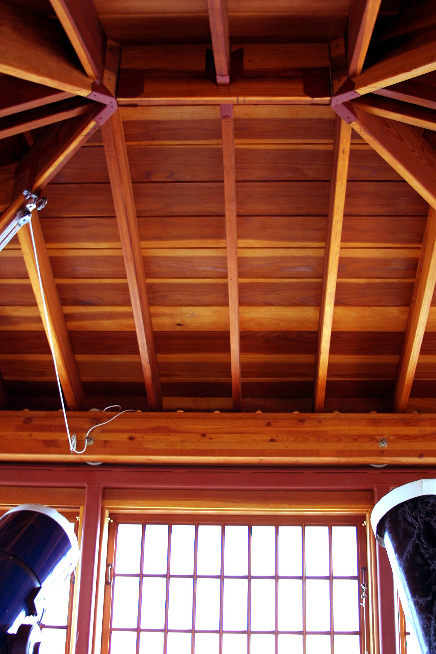
The main rolling roof structure is made of six huge laminated and
glued beams, two on each side to hold the wheels and one on each end
to form a box. The roof itself sits on top of the box and consists
of exposed redwood joists, redwood "V-Rustic" ceiling planks, plywood
for structural strength and cedar shakes on top. The whole structure
is very rigid and very heavy but it still moves smoothly and quietly.
For the walls between the steel structural members we used
conventional stick framing. The inside of the wall is more redwood to
match the ceiling; the outside is plain plywood for sheer strength
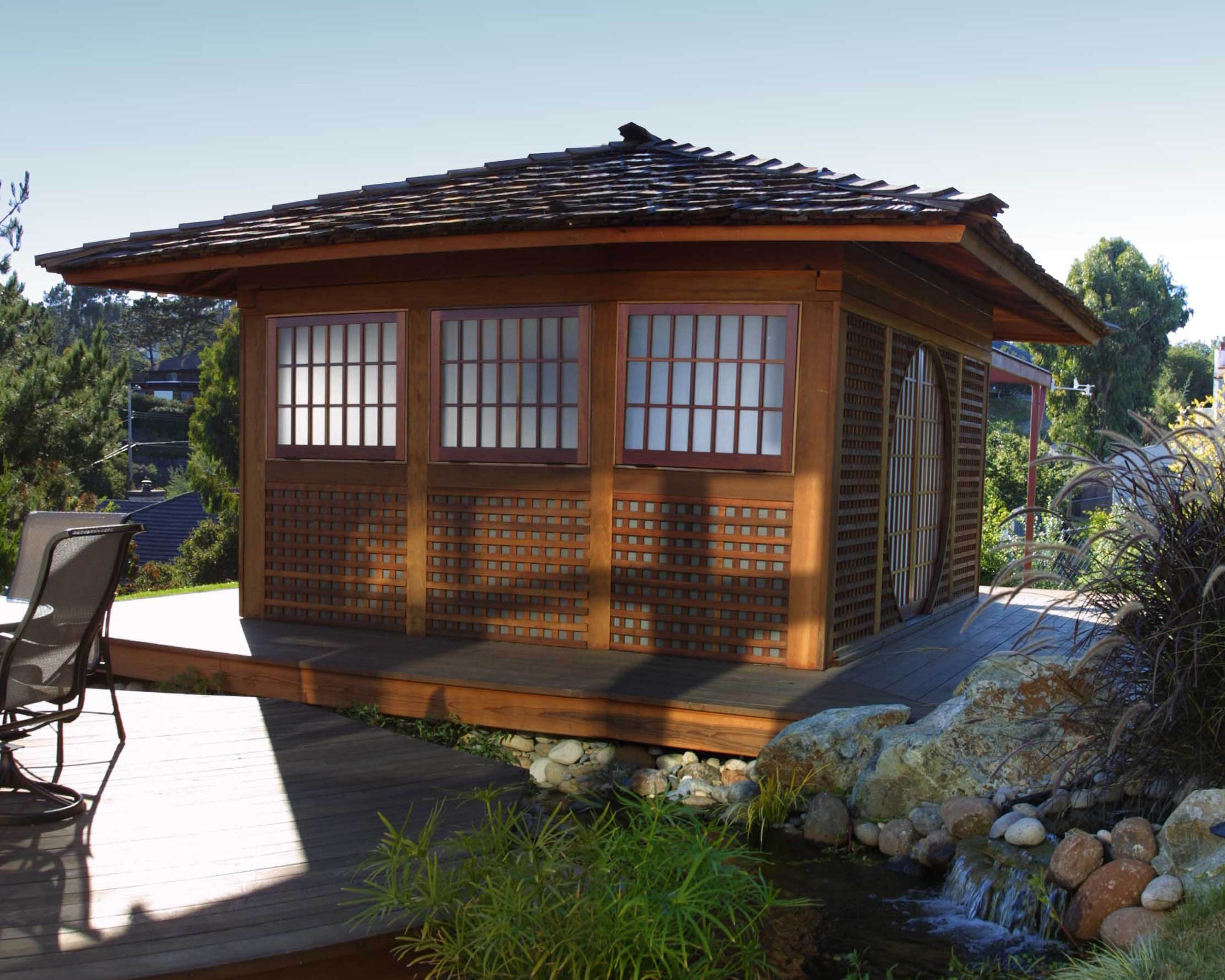
covered with redwood lattice for appearance. No insulation! The
windows are custom made individual pane panels made in the style of a
Japanese shoji screen. They're sand blasted for a frosted look from
the outside. They're hinged at the bottom to fold out and down. Each
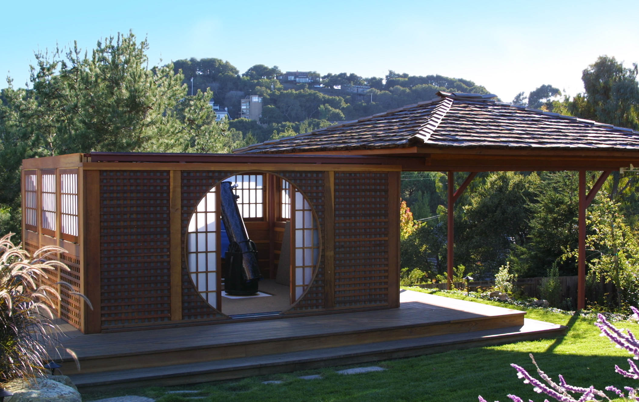
one is held closed by a simple pair of hooks and eyes. The door on
the north side is a pair of sliding panels identical in design to the
windows. They slide inside a round opening; in Japanese architecture
this is sometimes called a "Moon door", which I thought was fitting as
my main interest these days is lunar observing.
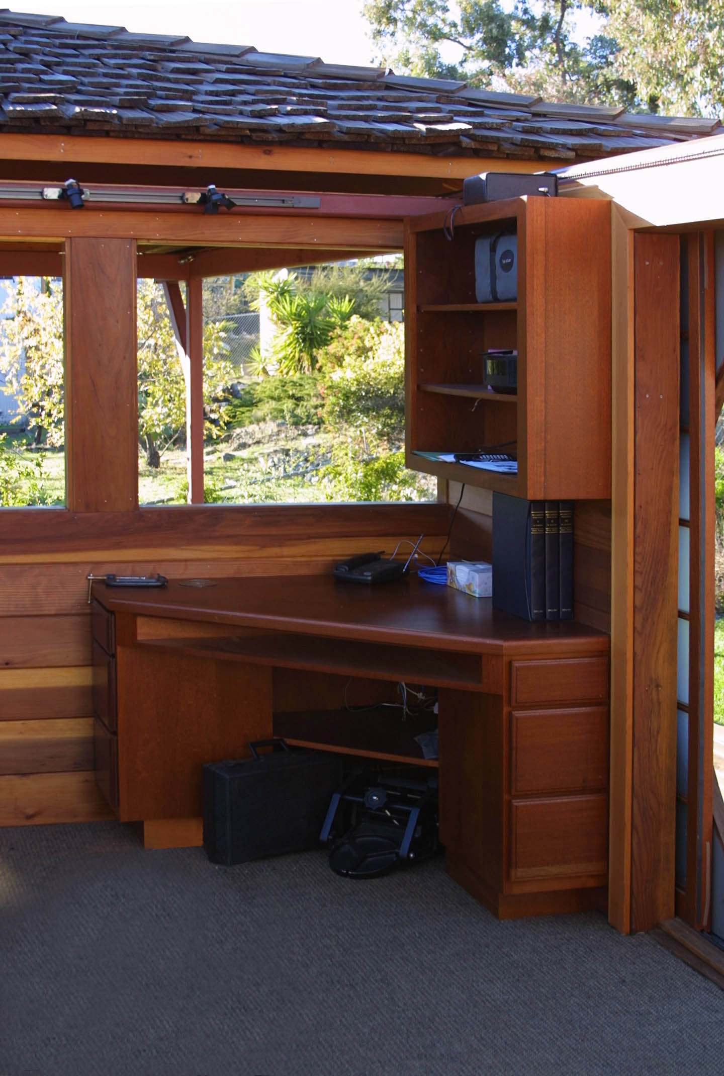
The finishing touches include carpeting, custom cabinets, desk and
bookcases, phone and ethernet wiring and a special heated case for
eyepieces.
It took 11 months and 6 days from when we started digging until we
were finally done; a long time but I'm very happy with the way it came
out!
Lessons Learned: What I Would Do Differently Next Time
I had to make the roof roll off to the west to avoid messing up my yard too
much. But this is a more serious compromise than I thought. I'm
loosing too much of the western sky, which is my darkest (though the
seeing is usually poor that low). This is problem is especially severe
for the western pier location. There are a couple possible solutions
other than the obvious rolling off to the north. First would be to
make the roof peak lower. Second would be to make the rails longer so
the roof could be pushed farther away. Third would be to have roll off
rails on the eastern side, too. This never occurred to me until long
after it was too late; I had just assumed that they would be way to
ugly. But not so! They actually look kind of neat (In My Humble Opinion).
The high walls make are much more of a problem for a Dobsonian than for an
SCT or a refractor. I designed it with my LX200 in mind. But when I
try to use my 10" f/6 Dob inside the observatory its low altitude
axis means that the top of the walls is much higher in the sky. An
equatorially mounted Newtonian would either have the same problem or
would necessitate the use of a ladder to reach the eyepiece. A really
big Dob would also need more floor space. Looks like my next scope
will have to be a refractor :-)
We get a lot of wind here. And as I was raised in San Diego, 50
degrees F and a 15 mph wind seems like an arctic blizzard to me. The
walls, high though they are, don't protect from the wind as much as I
would like. A dome looks a lot better when I'm shivering and going
back in for my ski suit in May! A dome was out of the question this
time but next time I think it might be the way to go. Or possibly a
split roll off (roof rolls two ways, joining in the middle with the
possibility of each half going past center) so that the opening could
be adjusted to fit the weather.
My concrete pier is unnecessarily big. All that extra mass didn't seem
to have any effect. Strength is not much of an issue with amateur
scopes. What is important is vibration damping and concrete isn't good at
that. My huge pier is not harmful but it's not helping much, either.
Even though it came out bigger than planned, the floor area could be a
little bigger. There's no room to pass between the scope and the wall
if the observing chair is in the way. Another two feet in each
direction would help. (Assuming the two scope layout; with just one
scope in the middle I think it would be fine.)
All that notwithstanding, I'm extremely happy with the end result. My
goals of having it both functional and aesthetically pleasing were
both fully achieved!
For more details and pictures see my WWW site at
http://obs.nineplanets.org/obs/obs.html
Postscript: Why "Ptolemy's Cafe"?
Ptolemy, the famous Greek astronomer and geographer, is variously quoted as
saying something like:
"I know that I am mortal and the creature of a day; but when I search
out the massed wheeling circles of the stars, my feet no longer
touch the earth, but, side by side with Zeus himself, I take my
fill of ambrosia, the food of the gods."
As it turns out, Ptolemy's theory of the solar system is wrong. But
this quote still captures a lot of what I feel when I roll open my
roof and spend a few quiet hours with the rest of the universe.
 Ptolemy's Cafe (north side). |
 The east side of the observatory and the deck between it and my house. |
 The roof rolls off to the west. |
 Plan of one of the eight wheels. |
 Digging the foundation piers required this massive machine. It had to pass between my neighbor's house and my gas meter with only a couple inches of clearance on each side. |
 A Boy and His Pier. The concrete block I'm standing on is connected to a concrete cylinder big enough around for me to fit inside and twice my height! |
 The interior ceiling and inside view of one of the windows. |
 The northwest corner with built-in desk and bookcase. The northeast corner has another bookcase and a cabinet holding the roof opening mechanism. |
 Hydraulically operated telescoping pier |
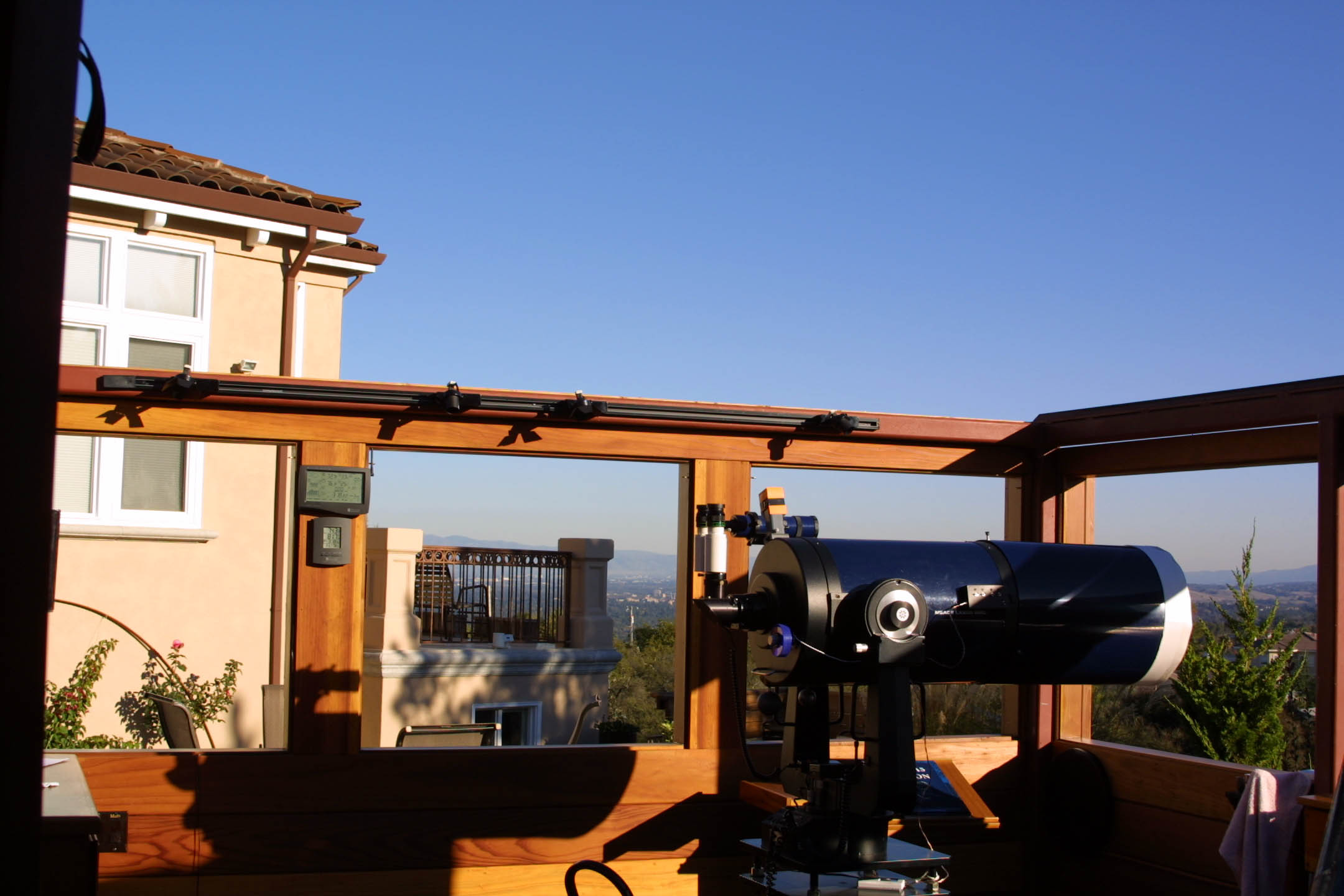
 Looking southeast from underneath the open roof with all the windows open. |
 View from inside toward the southeast. |
(Click the images for larger versions.) For more please see my WWW site. |
Bill Arnett; last updated:
2001 Mar 27