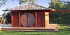
Here's the overall landscaping plan:
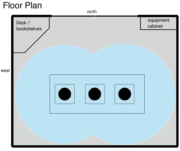 The observatory is 14 feet in the east-west direction and 11 1/2
feet in the north-south direction (interior measures). (And it is
lined up with the true directions within a few minutes of arc.) The
original plan called for 12x10 feet interior measure but by happy
accident interior and exterior measurements got swapped a couple times
and I gained a few square feet :-) This gives me plenty of room to
mount two scopes on piers, have some storage and working area and
still move around freely. It is surrounded by a 4 foot wide deck
which is about 18 inches above the surrounding ground level. The
walls are just under 7 feet high with the roof open.
The observatory is 14 feet in the east-west direction and 11 1/2
feet in the north-south direction (interior measures). (And it is
lined up with the true directions within a few minutes of arc.) The
original plan called for 12x10 feet interior measure but by happy
accident interior and exterior measurements got swapped a couple times
and I gained a few square feet :-) This gives me plenty of room to
mount two scopes on piers, have some storage and working area and
still move around freely. It is surrounded by a 4 foot wide deck
which is about 18 inches above the surrounding ground level. The
walls are just under 7 feet high with the roof open.
There is one giant block of concrete beneath the floor with three sets of pier attachment bolts. Thus I can have one scope in the middle or one on each end.
The door is on the north side. There are fold-down windows on the other three sides.
 I stole this design from
Chris Vedeler.
My structural engineer then beefed it up for my heavier
roof. The diagram at the left shows a cross section thru the wall.
There are 4 wheels on each side; each wheel is 6" diameter cast iron
with roller bearings (readily available from McMaster-Carr) with a 1000 lb load
rating. At first I thought that was way overkill but our best guess
at this point is that the roof weighs 6000 lbs so it's actually about
right.
I stole this design from
Chris Vedeler.
My structural engineer then beefed it up for my heavier
roof. The diagram at the left shows a cross section thru the wall.
There are 4 wheels on each side; each wheel is 6" diameter cast iron
with roller bearings (readily available from McMaster-Carr) with a 1000 lb load
rating. At first I thought that was way overkill but our best guess
at this point is that the roof weighs 6000 lbs so it's actually about
right.
 I did a lot of thinking about the opening mechanism. I had always
wanted a motorized one and when the roof was completed it was clear
that a motor was a requirement, not an option. The roof rolls nicely
and quietly but it takes a lot of effort to get it moving. I had an
old 1/2 horsepower garage door opener lying around so I hooked it up with a temporary
kludge and much to my surprise it moved the roof easily. So after a
lot of worry about how to run the chain and how to attach it to the
roof I ended up with a fairly simple solution but alas, this horrid
diagram is all the design documentation I have :-(
I did a lot of thinking about the opening mechanism. I had always
wanted a motorized one and when the roof was completed it was clear
that a motor was a requirement, not an option. The roof rolls nicely
and quietly but it takes a lot of effort to get it moving. I had an
old 1/2 horsepower garage door opener lying around so I hooked it up with a temporary
kludge and much to my surprise it moved the roof easily. So after a
lot of worry about how to run the chain and how to attach it to the
roof I ended up with a fairly simple solution but alas, this horrid
diagram is all the design documentation I have :-(
I didn't want to have chain go thru the wall and be exposed to the
weather. So I spliced the chain to some plastic coated steel aircraft
cable. The idea is that if the distance the roof has to travel (17 feet) is
less than the distance from the sproket to the point where the
cable/chain must go thru the wall then only cable need pass thru.
This meant folding the chain/cable path once but that turned out well
anyway since it put the opener itself down on the floor where it's
easy to work with.
 Attaching the cable to the roof was also a little tricky. If it was
attached solidly then the roof's inertia would put a huge shock load
on the motor and gears. But if I simply put a spring in the middle of
the cable then it wasn't possible to get the chain/cable tight enough
to prevent it from jumping off the motor's sprocket. The answer is
this: the cable makes a complete loop (not shown here) with no springs
so it can be tightened (via a turnbuckle at the opposite end from the
motor, also not shown) but it is attached to the roof with springs
(via the pins shown here). The result works quite well. It stays
tight and springs three or four inches on starting and stopping with
no apparent stress on the motor.
Attaching the cable to the roof was also a little tricky. If it was
attached solidly then the roof's inertia would put a huge shock load
on the motor and gears. But if I simply put a spring in the middle of
the cable then it wasn't possible to get the chain/cable tight enough
to prevent it from jumping off the motor's sprocket. The answer is
this: the cable makes a complete loop (not shown here) with no springs
so it can be tightened (via a turnbuckle at the opposite end from the
motor, also not shown) but it is attached to the roof with springs
(via the pins shown here). The result works quite well. It stays
tight and springs three or four inches on starting and stopping with
no apparent stress on the motor.
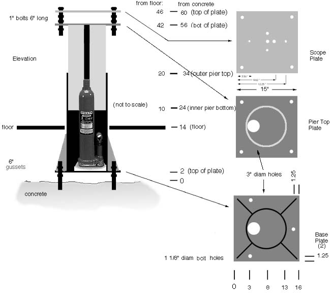
Below is the design diagram for the steel pier (which sits on top
of the concrete pier (funny terminology here). The idea is to be able
to move the scope up and down to get the optimum angle thru or over
the windows for objects near the horizon. It's all steel, 10" ID for
the bottom section, 10" OD for the top section. Not shown here is the
massive collar with 6 3/4" bolts which clamps the two sections
together. With the collar tight it is very solid. The top section
sits on a long throw hydraulic jack with an external hand pump.
 Bill Arnett